When digital astrophotography became feasible for amateurs at the turn of the century, the sensor of choice was a CCD (chargecoupled device). At this time, CMOS (complementary metal oxide semiconductor) chips were the domain of barcode readers and the like – cheap, but noisy. However, CMOS chips had an ace up their sleeve, which was a faster readout. This made them better for video applications than their more sedate CCD cousins. In-phone cameras with video capability were the new ‘must haves’ and CMOS became the digital technology of the connected age. Development switched over to CMOS, leading to major improvements, including low-light sensitivity and high resolution, the very things to arouse the interest of astro-imagers!
Both CMOS chips and CCD sensors use an array of pixels onto which photons arrive and release electrons from the silicon substrate. With a CCD, the charge developed within each pixel is transferred off the sensor, with each pixel being read individually by an analogue-to-digital converter (ADC) and changed to a digital value on a 16-bit scale. This design gives very consistent readings across all pixels and also enables pixels to be grouped together and read as a single unit, known as binning. CCDs remain the sensor of choice for demanding scientific applications such as photometry.
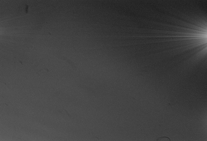
CMOS chips have many ADCs built into the sensor itself. All pixels are read simultaneously, which is quicker and reduces the amount of noise generated during the data collection (‘read noise’). However, the electronics within the sensor generate heat that causes pixels to release extra electrons, resulting in thermal noise and amp glow. The latter, which we’ll delve into in more detail later in the article, manifests itself as a brightening that appears from one or more edges of the chip. While CMOS cameras can have their pixels binned, this is done after each pixel has been read individually, so unlike with CCDs, read noise is not reduced by binning.
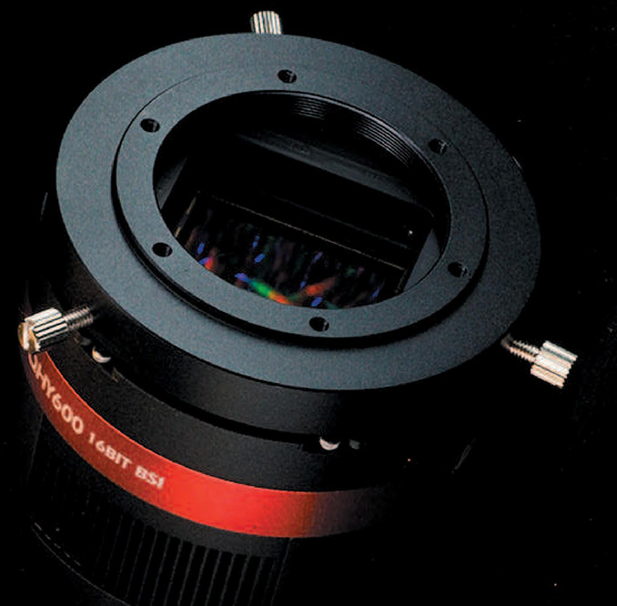
At the leading edge of CMOS chips in astro-imaging devices is the Sony IMX455. This chip has a full-frame format with over 60 megapixels, and yet it downloads in around half a second. It has an excellent full-well depth (the amount of light that can be recorded on each pixel) and dynamic range, very-low thermal and read noise, and produces no amp glow. CMOS has certainly come of age!
Choosing a camera
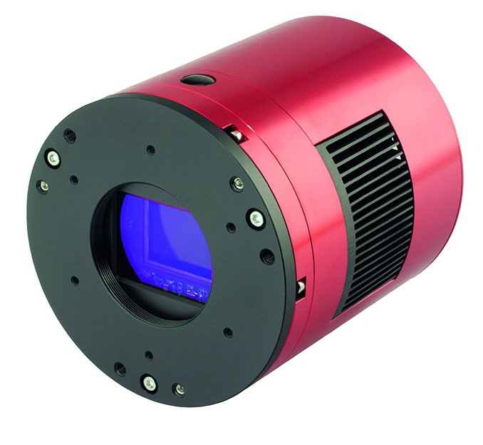
Nearly all DSLR cameras now have CMOS sensors and are capable of taking excellent astronomical images. However, dedicated deep-sky cameras have the major advantage of set-point cooling, the option of monochrome imaging and the easier integration of accessories such as off-axis guiders and filter drawers.
When choosing a camera, price will obviously focus the mind and the rapid development of CMOS cameras has made high-resolution, generously sized chips far more affordable. ZWO and QHY have been the market leaders with both manufacturers producing wellmade CMOS cameras. Atik now also has some excellent CMOS cameras and other manufacturers are joining the fray.
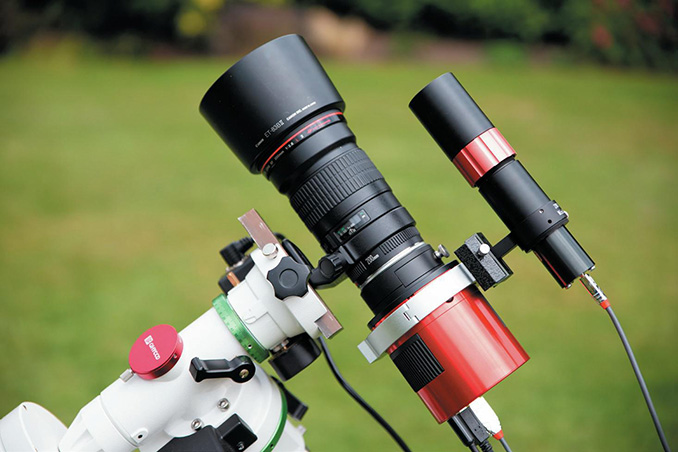
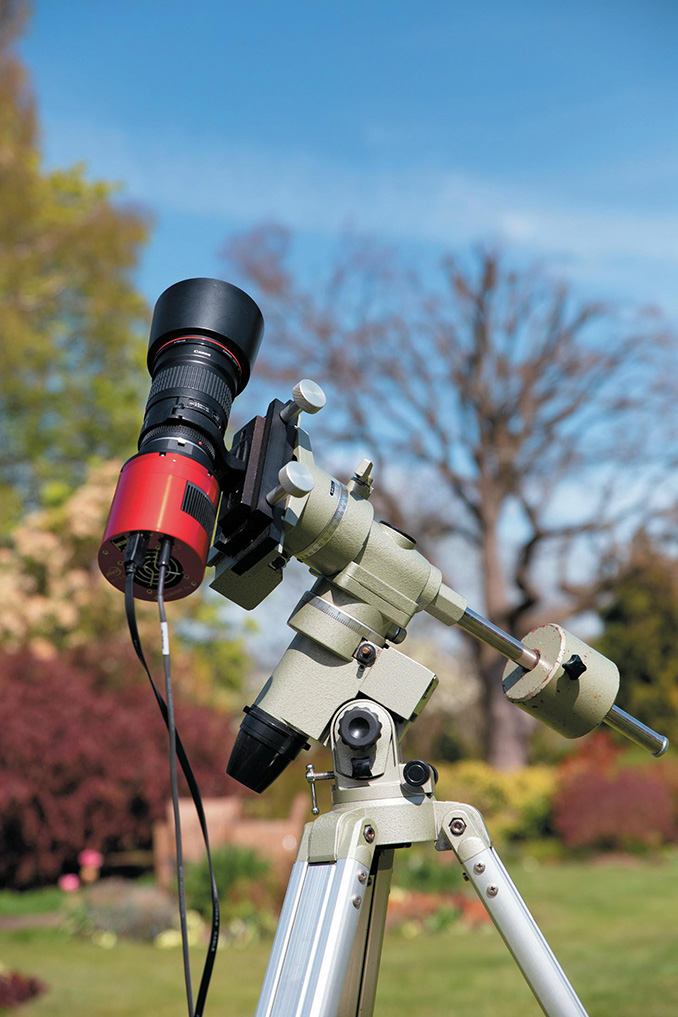
Generally, the larger the chip, the higher the price. Having decided on your budget, you will want a good match of camera to focal length, with smaller pixels being a better match for short focal lengths. A CMOS chip with small pixels is ideal when using short-focal-length refractors. With 2.4-micron pixels you can have excellent sampling with a 200mm camera lens, while even a 135mm lens will provide reasonable resolution for larger deep-sky targets.
You might also want to go for as large a chip as your optics and funds can cope with. A telescope with a focal length of around 1,000mm can become an excellent imager of small galaxies and planetary nebulae when used with a CMOS camera with a larger chip armed with pixels in the 4–5 micron range.
Development of CMOS sensors has led to major improvements in lowlight sensitivity and high resolution, the very things to arouse the interest of astro-imagers!
CMOS cameras are multitalented. A camera equipped with a Sony IMX183 CMOS chip and all the features required for deep-sky imaging, such as set-point cooling, can happily double up as an excellent planetary and lunar imager, making great use of its small 2.4-micron pixels. By selecting a region of interest and dropping the bit depth (the number of bits per pixel) to 10, you can be video imaging at 117 fps!
A camera such as the 46-megapixel ZWO 294MM used fully unbinned with 2.3-micron pixels can be paired with a 200mm lens to give a high resolution five-degree field of view. Binning 2×, the 4.6-micron pixels pair well with a 1,000mm focal length telescope for galaxy hunting.
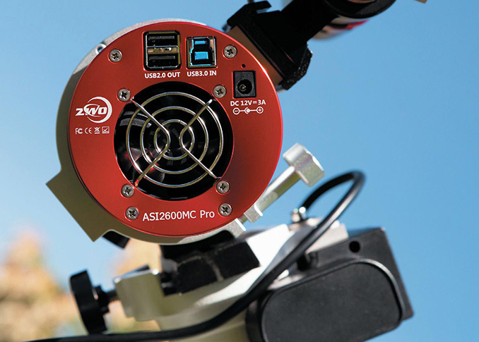
The ZWO 2600MC one-shot colour camera and its high-resolution, 26-megapixel APSsized chip, when used in conjunction with a dual narrowband-pass filter, could even turn the heads of hardcore mono-imagers!
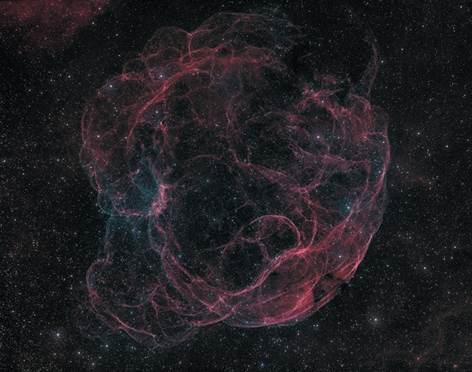
All CCD cameras are 16 bit, whereas CMOS cameras can be 12, 14 or 16 bit. Does this matter? You would imagine so. The analogue-to-digital converters on a 12-bit CMOS chip can convert the pixel values to brightness values of between 0 (black) and 4,095 (white). Compare this to a 16-bit chip that allows 65,536 brightness values – it is a massive difference. However, in practice this vast difference doesn’t create the limitation one might expect, and it is possible to do quite extreme histogram stretching to pull out faint details during processing of an image on a 12- bit chip. For example, the supernova remnant Simeis 147 is very faint, and its O-III signal is exceptionally so. Yet I found that a 12-bit ZWO ASI 1600 chip was up to the task.
So while the information given regarding quantum efficiency, full-well depth, dynamic range and read noise can be useful, in my experience it is perhaps not quite as vital in the real world as the pixel and chip size.
What camera settings to use
Unlike CCD cameras that have a fixed gain, the gain value of CMOS cameras is variable and determined by the user. The ability to control the gain is one of the key features of CMOS imaging, ensuring optimal performance of the camera in different imaging situations. As such, it is important to understand how to set a suitable value.
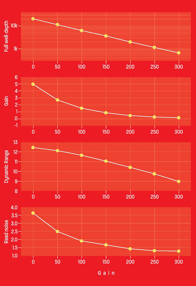
Camera manufacturers produce graphs showing the relationship between gain levels, full-well depth, dynamic range and read noise.
Full-well depth is closely linked to dynamic range and relates to how many electrons a pixel is able to hold. Dynamic range is defined as the ratio between the brightest thing visible in the image that isn’t pure white and the darkest thing that isn’t noise. So, for high-contrast images containing bright, colourful stars along with faint nebulosity, you need to preserve dynamic range as much as possible. However, for lesscontrasty targets this isn’t so critical.
Read noise is the result of inevitable errors brought about when ‘reading’ pixel values at the end of an exposure. It is important because it isn’t eliminated by stacking sub-exposures. In order to minimise the impact of read noise, your sub-exposures need to be of an adequate length for the read noise to be overwhelmed by thermal noise or light pollution (which, unlike read noise, do not impact on the progressive increase in the signal-to-noise ratio achieved by the stacking of multiple images). The lower the read noise, the shorter your sub-exposures can be. This is very useful when using narrowband filters, allowing sub-exposures to be reduced to five minutes or less. It is also a boon for unguided imaging and for poorly tracking mounts, since it enables short 30-second exposures on broadband targets.
The graphs for the ZWO ASI 1600 camera show a rapid initial decline in read noise when increasing the gain, followed by the curve starting to flatten out while the dynamic range and full-well depth continue to fall in a near linear manner. In other words, the graphs reveal a sweet spot, around a gain value of 150, for optimum read noise reduction with retention of dynamic range. Increasing the gain beyond this point delivers only small reductions in read noise but a sustained reduction in dynamic range, which would only be justified if imaging extremely faint targets from a dark-sky location. Many imagers like to use ‘unity gain’. This is the gain value at which one extra electron leads to an increase of the image brightness of one ADU (analogue to digital unit). There is nothing magical about unity gain, but in the case of the ASI 1600 it happens to be within the sweet spot mentioned above, so it is a reasonable choice for narrowband imaging, or if your equipment struggles with long exposures. Be aware though that unity gain isn’t always in such a helpful position, and your choice of gain value should be governed by the graphs, the nature of your target and your imaging equipment rather than this specific value.
At the leading edge of CMOS chips in astro-imaging devices is the Sony IMX455, which has a full-frame format with over 60 megapixels
Some CMOS chips have a magical highconversion-gain (HCG) switch that operates at and above a specific gain value. This switch delivers a significant drop in read noise and an increase in dynamic range, bringing it close to its zero gain value. Full-well depth isn’t significantly restored, however. Setting the gain at this point will be ideal for most situations except, perhaps, for images where star quality is of fundamental importance, as in the case of open clusters, or when hundreds of very short exposures stretch the storage and processing capabilities of your computer.
Offset
Pixels of zero value don’t respond to processing and can therefore result in unpleasant artefacts. To avoid this, each pixel has a built-in small initial value called an ‘offset’. The offset value is usually set by the manufacturer and will work well for the majority of situations. It comes at the cost of a small loss of dynamic range, which will normally be insignificant. However, if using a very high gain, it can be helpful to reduce the offset. To check that your offset value is suitable, take a bias frame (a non-illuminated frame with zero exposure time) and look at the histogram (the graph showing the brightness levels within your image) in your capture software. You may need to zoom in, but there should be a clear gap between the lowest value pixels and zero. Note that changing the offset requires a fresh set of calibration images. The offset delivered by a particular setting is less when using lower gain, so take care.
Calibration and amp glow
All long-exposure astro-images will contain artefacts that can be removed by careful image calibration. Most CMOS cameras feature thermoelectric cooling (TEC), which allows accurate, set-point cooling, unlike fan cooling, though some thermal noise will persist. This is eliminated by dark frames. Meanwhile, optical errors such as vignetting and dust motes are removed by flats, and fixed-pattern noise is managed by bias frames. However, CMOS chips produce two additional issues that aren’t encountered with CCDs. One is amp glow, which we’ve mentioned earlier in this article, and the other is the inconsistency of the electrical signal within bias frames.
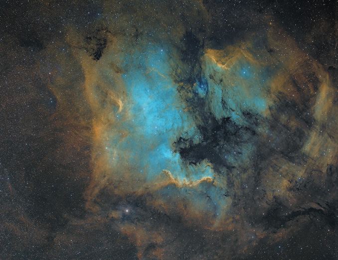
Although some recent CMOS chips such as the Sony IMX571 sensor do not produce amp glow, for most CMOS cameras this is an issue that you will have to deal with, particularly if you are using slower USB 2.0 data transfer, which can result in amp glow. Fortunately, removing amp glow isn’t difficult, and many CMOS cameras now feature a 256Mb image buffer that helps to reduce the glow. It is very important to realise that unlike other thermal noise, amp glow doesn’t increase in a linear manner over the length of the exposure, which makes it essential that dark-frame exposure times are identical to the exposure times of the light frames, in order to avoid residual amp glow artefacts. Any ‘optimise darks’ option appearing in calibration software must be unchecked even when your darks are properly matched. Failure to do this will, in all probability, result in very poor calibration.
The issue of the inconsistency of the electrical signal within bias frames isn’t a feature of all CMOS chips, but if it is a problem with your camera, then it is easily resolved by using ‘flat darks’ in place of bias frames. These are dark frames that are applied to flat frames. Again, it is essential that the flat darks’ exposure time matches that of the flat frames, and that any ‘dark frame optimisation’ option is unchecked. These short-exposure dark frames are much more consistent than bias frames and will give much better calibration if you have a camera with an ‘itchy chip’. It is worth experimenting by comparing your results when using bias frames and flat darks.
Processing CMOS images
Once you have calibrated your images, everything else is similar to images from a CCD camera. Alignment and integration of sub-frames is the same. Some processing software, such as PixInsight, has routines that require information regarding the value of the camera gain. This can easily be discovered from the gain graph. Histogram stretching, contrast enhancement and noise reduction are all carried out in exactly the same way.
After a short period of familiarisation, you will find a CMOS camera easy to use and capable of delivering remarkable images.
Martin Bradley is an experienced astro-imager based in light polluted, cloudy Chesterfield.